
CherryMAX® Blind Rivet
Overview

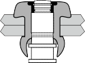
CherryMAX® is a locked spindle blind rivet with a visibly inspectable mechanical locking device and its own installation washer, which eliminates the problems resulting from worn tool anvils. It is called a "bulbed" fastener due to its large blind side bearing surface, developed during the installation process. CherryMAX® rivets are used in thin sheet applications and for use in materials that may be damaged by other types of blind rivets.
The CherryMAX® rivet is the most reliable, high strength structural fastener with visual inspectability in the world today. It features the "Safe-lock" locking collar for more reliable joint integrity, and meets the requirements of PS-CMR-3000.
CherryMAX® tooling provides the simplest, most trouble-free installation tooling system. CherryMAX® fasteners are currently available in 1/8" through 1/4" diameters in both nominal and 1/64" oversize diameters. The tools use a single pulling head to install many diameters, head configurations, and material combinations.
Features
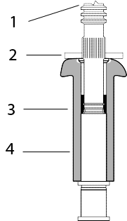
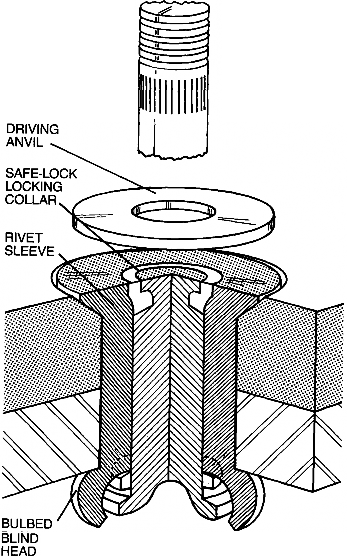
- A fully-serrated stem with break notch, shear-ring and integral grip adjustment cone.
- A driving anvil to ensure a visible mechanical lock with each fastener installation.
- A separate, visible and inspectable locking collar that mechanically locks the stem to the rivet sleeve.
- A rivet sleeve with recess in the head to receive the locking collar
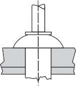
Installation
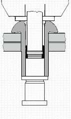
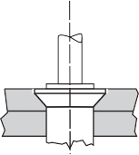
Stage 1
The CherryMAX® Rivet is inserted into the prepared hole, and the pulling head (installation tool) is slipped over the rivet’s stem. Applying a firm, steady pressure, which seats the rivet head, the installation tool is then actuated.
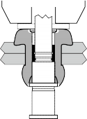
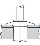
Stage 2
The pulling head holds the rivet sleeve in place as it begins to pull the rivet stem into the rivet sleeve. This pulling action causes the stem shear ring to upset the rivet sleeve and form the "bulbed" blind head. Formation of the rivet sleeve’s "bulbed" blind head is complete.
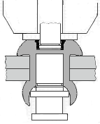
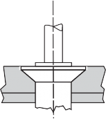
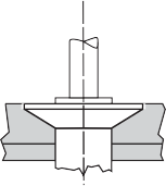
Stage 3
The continued pulling action of the installation tool causes the stem shear ring to shear from the main body of the stem as the stem continues to move through the rivet sleeve. This action allows the fastener to accommodate a minimum of 1/16" variation in structure thickness. The Locking Collar then contacts the Driving Anvil. As the stem continues to be pulled by the action of the installation tool, the "Safe-lock" Locking Collar deforms into the rivet sleeve head recess.
Stage 4
The "Safe-lock" Locking Collar fills the rivet sleeve head recess, locking the stem and rivet sleeve securely together. Continued pulling by the installation tool causes the stem to fracture at the break notch, providing a flush, burr-free, inspectable installation.
Benefits
Driving Anvil
A driving anvil is part of each CherryMAX® Rivet assembly. This Driving Anvil eliminates wear and replacement of expendable installation tool components,
considerably extending the life of the installation tool.
It also allows a single pulling head to install:
- 1/8", 5/32", and 3/16" Nominal and Oversize Diameter Rivets.
- Protruding, 100° Flush and 100° Flush Shear, Unisink, and 120° Flush Head Styles
- All CherryMAX® Rivet grip lengths
- All CherryMAX® Rivet sleeve/stem material combinations
Locking Collar
- The CherryMAX® Rivet features the "Safe-lock" Locking Collar which enhances joint integrity and reliability.
- The "Safe-lock" Locking Collar is preformed on the stem during a sub-assembly operation, then deforms into the rivet sleeve head recess during installation, locking the rivet sleeve and stem together.
- The "Safe-lock" Locking Collar is visible and inspectable after installation.
- The "Safe-lock" Locking Collar installs flush with the rivet sleeve head.
- The "Safe-lock" Locking Collar has been approved by several OEMs for use in engine inlets and components.
Rivet
The CherryMAX® Rivet is available in both nominal and 1⁄64" oversize shank diameters and is available in four material combinations:
- 5056 Aluminum Sleeve/Alloy Steel Stem (50KSI Shear)
- 5056 Aluminum Sleeve/Cres Stem (50KSI Shear)
- Monel Sleeve/Cres Stem (75KSI Shear)
- INCO 600 Sleeve/INCO X-750 Stem (75KSI Shear)
Tooling Simplicity
- Lightweight, non-shifting installation tools require no adjusting.
- Limited access capability with Right Angle and Offset Pulling Heads and Extensions for greater reach and "Split" tools for special applications including automation and robotics.
Bulbed Blind Head
Provides a large bearing surface area on the blind side of the structure, giving dependable results, even when installed in difficult thin sheet stack-up applications.
Part Numbering System
Part Number Example: CR3 24 2 -6 -04
- CR3
- CherryMAX® Rivet
- 24
- Rivet Type & Material Combination - see Product Catalog
- 2
-
Head Style
- Odd Number = Protruding Head
- Even Number = Flush Head
- -6
- Rivet Diameter in 32nds of an inch (-6 = 6/32 = 3/16)
- -04
- Maximum Grip Length in 16ths of an inch (-04 = 4/16 = 1/4)
Head Styles
Universal (MS20470)
For protruding head applications. Available in both nominal and oversize.
100° Flush (MS20426)
For countersunk applications. Available in both nominal and oversize.
100° Flush (NAS1097)
For thin top sheet, machine countersunk applications. Available in nominal only.
Unisink
A combination flush and protruding head for use in very thin top sheets. Eliminates need for double-dimpling. Available in oversize only.
120° Flush
A large diameter, shallow flush head providing a wide bearing area in thin top sheet applications. Available in oversize only.
Diameter
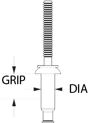
Bulbed CherryMAX® rivets are offered in 1⁄8" (-4), 5/32" (-5), 3/16" (-6) and 1⁄4" (-8) shank diameters. They are available in nominal and 1/64" oversize. A gold colored driving anvil identifies nominal diameter. A silver colored driving anvil identifies oversize diameter.
Grip
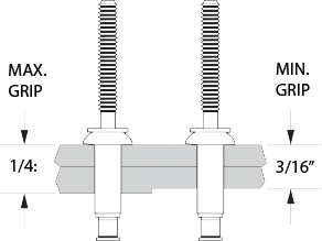
The grip range of all CherryMAX® rivets is in increments of 1/16", with the last dash number indicating the maximum grip length in 16ths.
For example, -04 grip rivet has a grip range of 3/16" (.188) to 1/4" (.250).
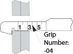
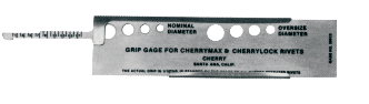
To determine the proper rivet grip to use, measure the material thickness with a Cherry 269C3 grip selector gage, as illustrated in the diagram and the video tutorial. Always read to the next higher number.
Mechanical Properties*
| Materials | Ultimate Shear Strength | Maximum Temperature | |
|---|---|---|---|
| Sleeve | Stem | ||
| 5056 Aluminum | Alloy Steel | 50,000 psi | 250° F |
| 5056 Aluminum | CRES | 50,000 psi | 250° F |
| Monel | CRES | 75,000 psi | 900° F |
| Inco 600 | Inco X-750 | 75,000 psi | 1400° F |
*At room temperature
| Rivet Diameter | Sheet Thickness | Single Shear | Tensile | ||||||||||
|---|---|---|---|---|---|---|---|---|---|---|---|---|---|
| Aluminum | Monel | Inco | Aluminum | Monel | Inco | ||||||||
| Nom. | O/S | Nom. | O/S | O/S | Nom. | O/S | Nom. | O/S | O/S | ||||
| 3212 | 3242 | 3522 | 3552 | 3852 | 3212 | 3214 | 3242 | 3522 | 3524 | 3552 | 3852 | ||
| 3213 | 3243 | 3523 | 3553 | 3853 | 3213 | 3224 | 3243 | 3523 | 3553 | 3853 | |||
| 3214 | 3245 | 3524 | 3555 | 3222 | 3245 | 3555 | |||||||
| 3222 | 3246 | 3556 | 3223 | 3246 | 3556 | ||||||||
| 3223 | 3252 | 3252 | |||||||||||
| 3224 | 3253 | 3253 | |||||||||||
| 3255 | 3255 | ||||||||||||
| 1/8 (-4) | 2 x .156 | 664 | 814 | 995 | 1220 | 1220 | 285 | 250 | 345 | 400 | 360 | 490 | 570 |
| 5/32 (-5) | 2 x .187 | 1030 | 1245 | 1545 | 1865 | 1865 | 445 | 390 | 530 | 635 | 555 | 740 | 860 |
| 3/16 (-6) | 2 x .219 | 1480 | 1685 | 2215 | 2525 | 2525 | 635 | 560 | 710 | 890 | 800 | 1000 | 1160 |
| 1/4 (-8) | 2 x .281 | 2615 | 2925 | 3920 | 4390 | 4390 | 1125 | 1000 | 1260 | 1570 | 1410 | 1755 | 2030 |